7-Segment LCD Clock
All sources can be found on GitHub . A German summary of this project can be found on mikrocontroller.net .
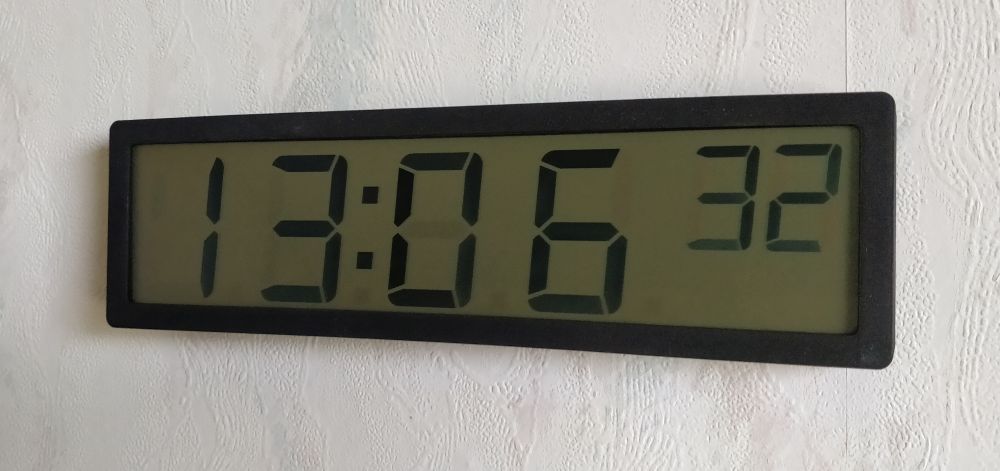
Let's start with the end result:
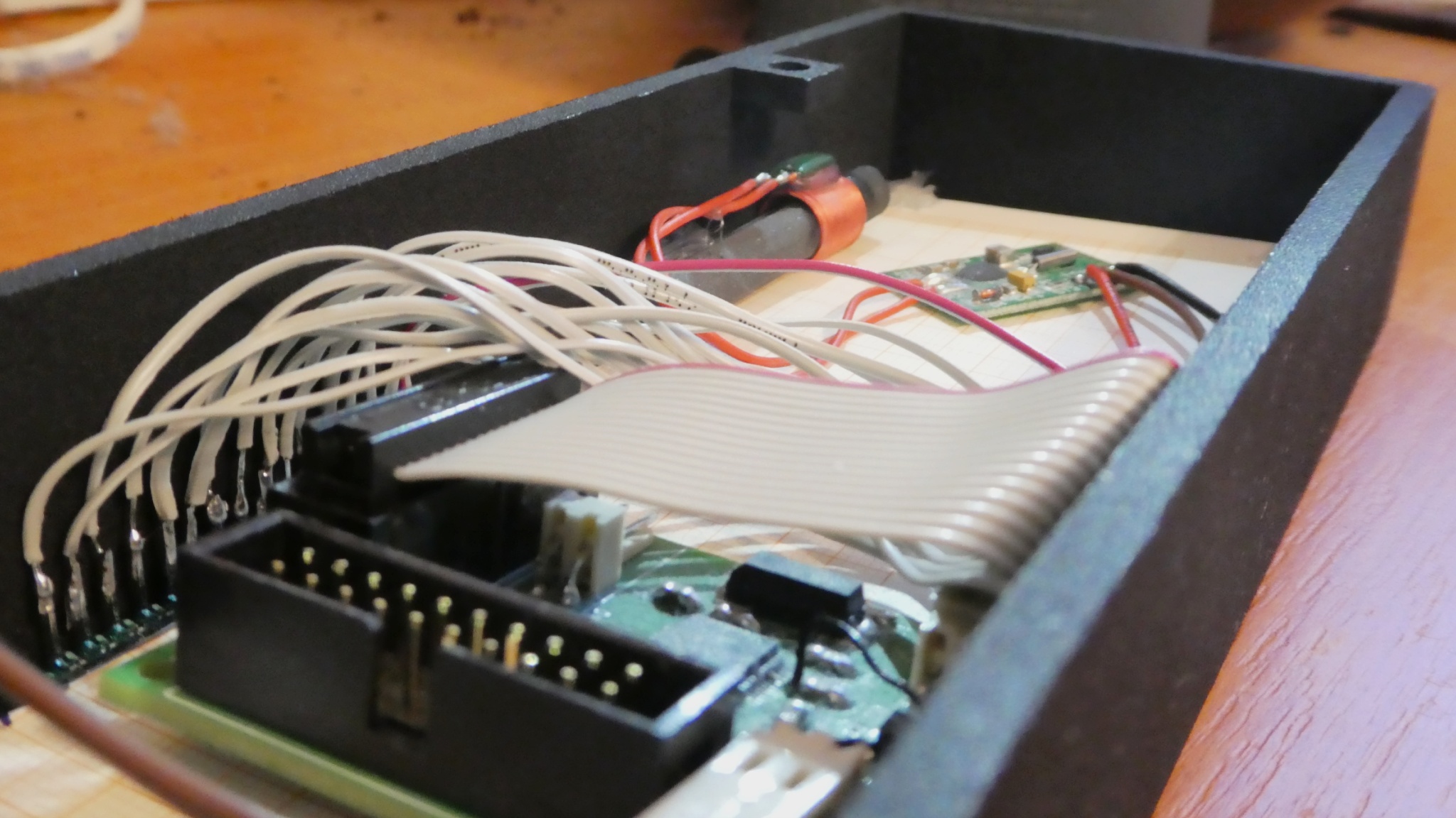
The case is 3D-printed and the STL-file can be found in the GitHub repository. Here a picture of the backside of the case:
Concept
The clock is powered by four normal AAA batteries, which leads to a voltage range of about 6.4 V to 3.2 V. After a simple reverse polarity protection built with a single MOSFET, the TPS70630 converts this input voltage to the required 3 V.
The microcontroller, a STM32L073CZ , uses the internal boost/buck-converter to generate the LCD voltage (see pin 1) and furthermore directly powers a DCF77 module (pin 42 and 43). A simple clock crystal is used as source clock for the internal RTC (pin 3 and 4).
Since the DCF77 signal can be very bad in eastern Austria, I implemented a very
sophisticated parser with error correction heavily inspired by a great article
about this topic by Georg Johann (dcf77_parser.cpp ).
Unfortunately, one still has to be very lucky for the time to synchronize during
the day. Therefore, the clock synchronizes itself only after power-up and on
Sunday mornings.
The LCD panel was simply connected to the outputs of the microcontroller. There is nothing notable to say about that. The only problem with this panel is that LCD ghosting can be an issue. This is due to the way multiplexed LCD panels work: Even if a segment is off it has to be driven with a small voltage to avoid damaging it. On low quality LCD panels this small voltage might be enough to make the disabled segment visible for a careful observer.


